

PAX IM30 PCI 6 Quick Setup Guide of Contents
Contents Checklist
Congratulations on receiving your PAX Technology payment terminal. We do hope you enjoy it! Please check the contents after unpacking. If any components are missing or a page is missing from the Quick Setup Guide, please contact your PAX dealer. The box you have just opened should contain the following items:
| Name | Qty. |
| IM30 Unattended Payment Terminal | 1 |
| M4 Nuts | 4 |
| M4 Screws | 4 |
| Mounting Bracket | 1 |
Product Description
Front View
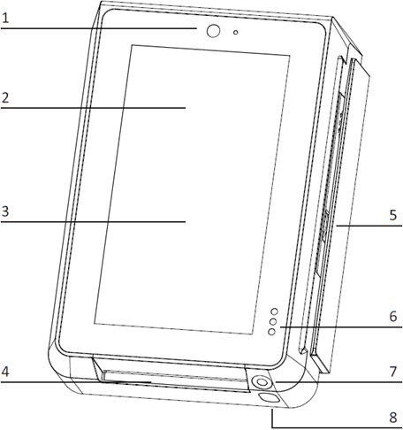
- Front Facing Camera
- Contactless Card Reader Interface
- LCD Touchscreen
- Smart Card Reader
- Magnetic Strip Card Reader
- Proximity and Light Detector
- Code Scanning Camera
- Camera Lighting
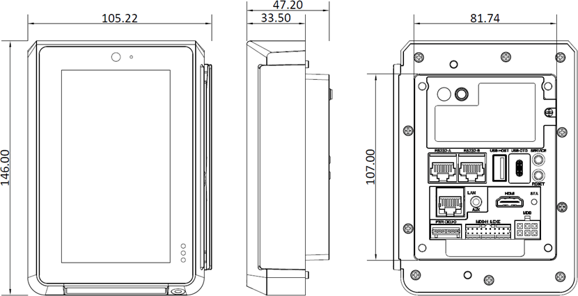
Back View
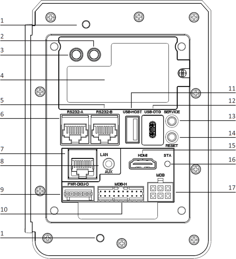
- Anti-removal Switches
- 4G Antenna SMA Connector (Optional)
- GPS Antenna SMA Connector (Optional)
- 4G Module & SIM Card Slot
- RS232-B (RJ45)
- RS232-A (RJ45)
- Ethernet Port (RJ45)
- Auxiliary Port (Mic + Speaker)
- Digital IO Port
- MDB Master Port
- USB Type-A Port
- USB Type-C Port
- Service Button
- Reset Button
- HDMI Port
- Status Indicator LED
- MDB Slave Port
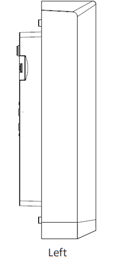
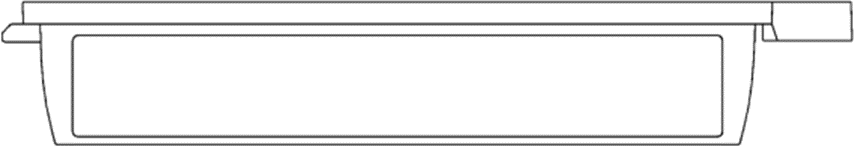
Left View
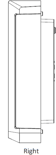
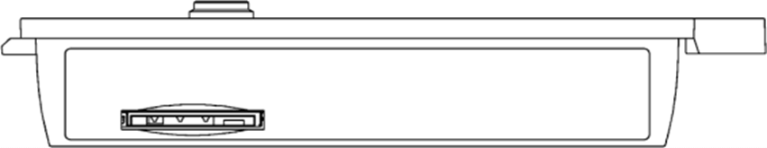
Right View
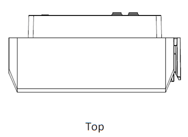
Top View
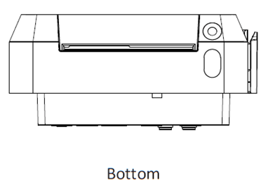
Bottom View
Installation
4G Module SIM and SAM Cards
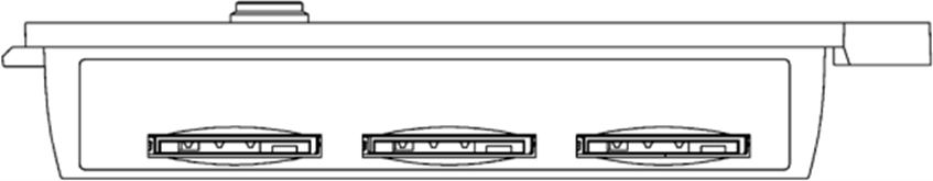
Certain configurations of the IM30 will have a 4G network module; in these configurations, you can install a SIM card. Unscrew the 4G network module and remove it to reveal the SIM card slot on the bottom of the module. Push the card into the slot with the contacts facing up and the clipped corner of the card facing towards the module. Certain configurations of the IM30 will have physical SAM card slots available. You may similarly install SAM cards in the SIM cards (make sure to use the appropriate card slots as indicated in Figure 6: 4G module, SIM (left) and SAM (middle and right) card slots.
SAM Cards
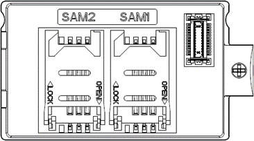
The IM30 has two dedicated SAM card slots, which can be accessed on the main body of the IM30 after the 4G network module (or the empty back cover) is removed. Open the card mount by sliding the card mount in the “OPEN” direction indicated on the mount, then insert a SAM card with the contacts facing the IM30 and the clipper corner oriented to the upper left. Lock the card mount by pressing it to the contacts and sliding it in the “LOCK” direction indicated on the card mount.
Note: Do not power on the IM30 while installing or removing SIM or SAM cards. To reassemble the device, slide the two plastic tabs on the left of the module into the corresponding slots on the main body of the IM30, then insert the 4G network board into the board-to-board connector. Finally, locked the module in place using a screwdriver.
Device Dimensions
Device Installation
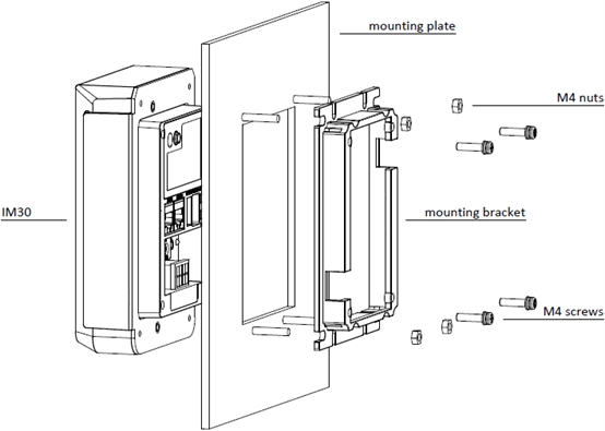
- Measure the thickness of the mounting plate, this is used later in step 4.
- The back face of the mounting plate should have four stud bolts corresponding to the mounting points located on mounting bracket. Slide the mounting bracket into place with the orientation shown in figure 9 and then fix it in place with four M4 nuts.
- Slide the IM30 unit into the mounting plate with the orientation shown in figure 9. The back portion of the device should rest securely inside the mounting bracket.
- If the mounting plate is ≤ 4mm thick, apply a torque of 0.6 ~ 0.8 Nm to the four M4 screws included with your IM30 unit to secure the IM30 to the mounting bracket. If the mounting plate is more than 4mm thick, obtain M4 screws with the following thread length and use them instead: (mounting plate thickness + 10mm) ≤ thread length ≤ (mounting plate thickness + 14mm)
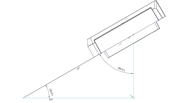
Note: The IM30 is intended to be installed 90° vertically to a maximum of 60° tilt from the vertical incline surface; ingress protection rate at IP65 is not guaranteed if the mounting surface deviates from this. Please refer to the picture below.
Instructions
Power on/off
Power on: Plug the IM30 into an appropriate power source via the MDB port, the digital IO port, or the RS232-A RJ45 port.
Power off: Disconnect the IM30 from the power source it is connected to.
Contactless Transactions
When the device is ready to accept a contactless transaction, the contactless icon should appear on screen. Orient the card or NFC device parallel to the screen and then hold it at a distance of 4 cm or less directly above the contactless icon.
Code Scanner Transactions
When the device indicates on screen that it is ready to scan a 1D or 2D code, orient the code parallel to the code scanning camera and then place it directly in front of the camera.
Environmental Conditions
Storage Temperature: -20°C ~ 70°C
Operating Temperature: 0°C ~ 50°C
Relative Humidity: 5% ~ 95% (non-condensing)
Maintenance and Usage
- If any cables become damaged, seek a replacement.
- Do not insert unknown materials into any port on the IM30, this may cause serious damage to the device.
- If repairs are required, please contact a professional technician instead of attempting them on your own.
- The IM30 contains tamper-proofing features; these circuits will trigger if the device is disassembled, at which point it will have to be rearmed before the device is ready to resume operation.
- The IM30 is designed for outdoor use; however, during normal use its surface should still be keep clear of dirt and possible liquid contaminants.
- While the IM30 is designed to resist ingress of dust and liquids, it is not designed to resist pressurized liquids such as water hoses. Keep the back of the device away from dust and liquids as much as possible.
- Make sure the various cables connect to provide the appropriate voltages at the proper pins.
Index of Icons
- Dispose of in a professional recycling manner
- Class II equipment
- For indoor use only
- Energy efficiency marking
- AC voltage
- DC voltage
Compliance Statements
FCC Compliance Statement
This device has been tested and found to comply with the limits for a Class B digital device, pursuant to Part 15 of the FCC Rules. These limits are designed to provide reasonable protection against harmful interference in a residential installation.
This equipment generates, uses, and can radiate radio frequency energy and, if not installed and used in accordance with the instructions, may cause harmful interference to radio communications.
However, there is no guarantee that interference will not occur in a particular installation. If this equipment does cause harmful interference to radio or television reception, which can be determined by turning the equipment off and on, the user is encouraged to try to correct the interference by one or more of the following measures:
- Reorient or relocate the receiving antenna.
- Increase the separation between the equipment and receiver.
- Connect the equipment into an outlet on a circuit different from that to which the receiver is connected.
- Consult the dealer or an experienced radio/TV technician for help.
FCC Note
Caution: Any changes or modifications not expressly approved by the manufacturer could void the user’s authority to operate this equipment.
RF Exposure Information
This device meets the government’s requirements for exposure to radio waves.
This device is designed and manufactured not to exceed the emission limits for exposure to radio frequency (RF) energy set by the Federal Communications Commission of the U.S. Government.
This device complies with FCC radiation exposure limits set forth for an uncontrolled environment. In order to avoid the possibility of exceeding the FCC radio frequency exposure limits, human proximity to the antenna shall not be less than 20 cm during normal operation.
ISED Notice
This device complies with Industry Canada license-exempt RSS standard(s). Operation is subject to the following two conditions:
- This device may not cause interference, and
- This device must accept any interference, including interference that may cause undesired operation of the device.
Le présent appareil est conforme aux CNR d’Industrie Canada applicables aux appareils radio exempts de licence. L’exploitation est autorisée aux deux conditions suivantes:
- L’appareil ne doit pas produire de brouillage, et
- L’utilisateur de l’appareil doit accepter tout brouillage radioélectrique subi, même si le brouillage est susceptible d’en compromettre le fonctionnement.
The device is restricted to indoor use only when operating in the 5250 to 5350 MHz frequency range in order to reduce the potential for harmful interference.
Le dispositif a étéutilisé pour la construction de la bande 5150 à 5250 MHz pour la consommation de matériel pour réduire le potentiel pour les systèmes de télévision mobiles.
CAN ICES-003 (B)/NMB-003(B)
This Class B digital apparatus complies with Canadian ICES-003.
Cet appareil numérique de la classe B est conforme à la norme NMB-003 du Canada.
ISED RF Exposure Statement
This device complies with ISED RSS-102 RF exposure limits set forth for an uncontrolled environment. In order to avoid the possibility of exceeding the IC RSS-102 RF exposure limits, human proximity to the antenna shall not be less than 20 cm (7.87 inches) during normal operation.
Cet appareil est conforme aux limites d’exposition aux rayonnements de la CNR-102 définies pour un environnement non contrôlé. Afin d’éviter la possibilité de dépasser les limites d’exposition aux fréquences radio de la CNR-102, la proximité humaine à l’antenne ne doit pas être inférieure à 20 cm (7.87 pouces) pendant le fonctionnement normal.
Battery Warning
Do not ingest battery, Chemical Burn Hazard.
This product contains a coin/button cell battery. If the coin/button cell battery is swallowed, it can cause severe internal burns in just 2 hours and can lead to death.
Keep new and used batteries away from children.
If the battery compartment does not close securely, stop using the product and keep it away from children.
If you think batteries might have been swallowed or placed inside any part of the body, seek immediate medical attention.
Trademark Recognition
Although PAX Computer Technology (Shenzhen) Co., Ltd. strives to maintain the accuracy of the information presented in this document, it reserves the right to change product specifications without prior notification and does not guarantee that the material presented herein will accurately reflect the set up, installation, or use of PAX products.
PAX Technology, Inc. reserves the right to change product technology specifications without prior notification.
PAX continually invests to maintain its high-quality products up to date with the latest certifications; therefore, a comprehensive list can be requested via the website’s contact form or through downloadable product brochures.
PAX Technology, Inc.
North American Headquarters:
8800 Baymeadows Way West
Suite #500 / Floor 5
Jacksonville, FL 32256
Phone: +1 877 859 0099
Email: [email protected]
Website: www.pax.us