IM25 Quick Setup Guide
PAX IM25 Quick Setup Guide Table of Contents
Contents Checklists
Congratulations on receiving your PAX Technology payment terminal. We do hope you enjoy it! Please check the contents after unpacking. If any components are missing or a page is missing from the Quick Setup Guide, please get in touch with your PAX dealer. The box you have just opened should contain the following items:
| Name | Qty. |
| IM25 Unattended Payment Terminal | 1 |
| IM25 Mounting Bracket | 1 |
| M4 Nuts | 4 |
| M4 Screws | 4 |
| 4G Antenna (Optional)* | 1 |
* The availability and configuration of optional modules are dependent on the model number of the IM25 unit.
Product Description
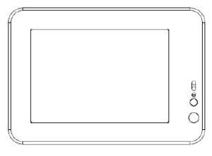
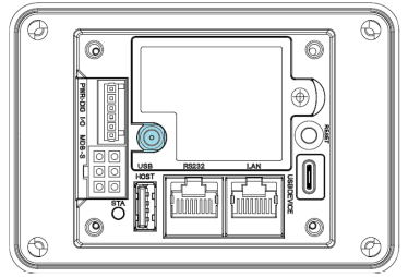
Front View
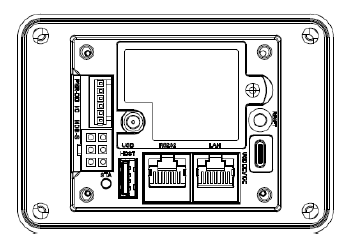
Back View
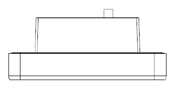
Top View
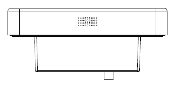
Bottom View
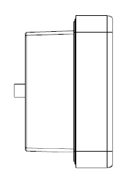
Left View
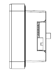
Right View
Installation
SAM Cards
The IM25 has 2 micro-SIM (2FF) sized SAM card slots.
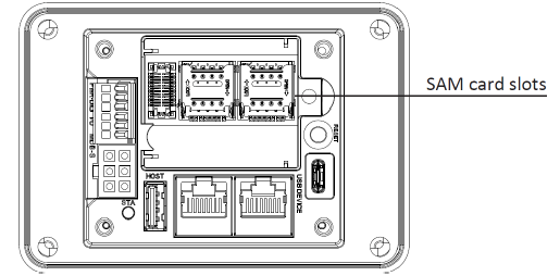
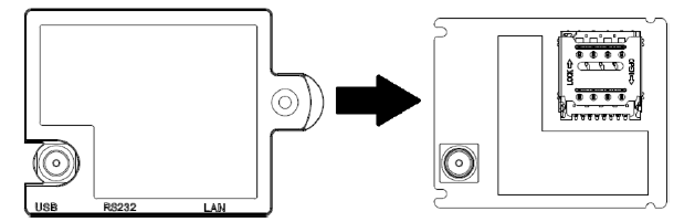
The SAM card slots are located under the removable back cover of the IM25. To configure the IM25 with a 4G network board, both the back cover and the 4G network board must be removed to access the SAM card slots. To install a SAM card in the IM25:
- Remove the back cover of the IM25 by unscrewing it from the body of the device.
- Once the cover is removed, the 4G network board is visible. Remove the 4G network board by holding the SMA connector and pulling away from the body of the device (skip this step if your IM25 model does not have a 4G network board).
- The SAM card slots are visible on the main body of the IM25.
- Open the card mount and insert a card with the contacts facing the board and the clipped corner of the card aligned with the card slot, then lock the mount with the card inside.
- Reassemble the IM25 by replacing the back cover and screwing it in place.
SIM Card Installation
Certain configurations of the IM25 have a 4G network board. These devices have 1 micro-SIM (2FF) sized SIM card slot.
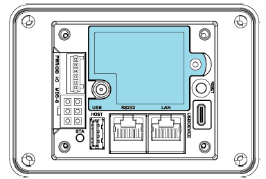
The SIM card slot is located on the 4G network board of the IM25. To install a SIM card in the IM25:
- Remove the back cover of the IM25 by unscrewing it from the body of the device.
- Once the cover is removed, the 4G network board and the SIM card slot are visible.
- Open the card mount and insert a card with the contacts facing the board and the clipped corner of the card aligned with the card slot, then lock the mount with the card inside.
- Reassemble the IM25 by replacing the back cover and screwing it in place.
4G Module
Certain configurations of the IM25 have a 4G cellular network module. These devices have a SMA antenna connector located on the back of the IM25 to which a 4G antenna can be attached. There are multiple possible 4G module configurations depending on the locality the IM25 is designed to be used in.
Option 1 Specification (EC200A-EU)
- LTE Bands: 1/3/5/7/8/20/28/38/40/41
- WCDMA: 1/5/8
- GSM: 2/8
Option 2 Specification (EC25-J)
- LTE Bands: 1/3/8/18/19/26/41
- WCDMA: 1/6/8/19
- GSM: 850/900/1800/1900 MHz
Option 3 Specification (NL668-AM)
- LTE Bands: 2/4/5/12/13/17/66/71
- WCDMA: 2/4/5
PAX Antenna
- Dipole antenna with magnetic base
- 1 meter cable
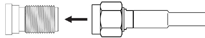
To install an antenna simply screw the SMA plug at the end of the antenna cable onto the SMA connector jack at the back of the IM25. The base of the dipole antenna is magnetized and can adhere to appropriate surfaces, it is also capable of standing on most flat surfaces so long as too much force isn’t applied to the cable.
Device Dimensions
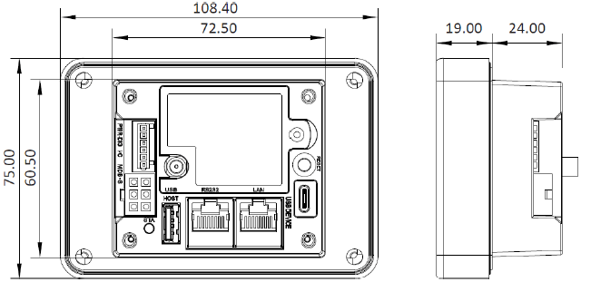
Note: Device dimensions are presented in millimeters (mm).
Device Installation
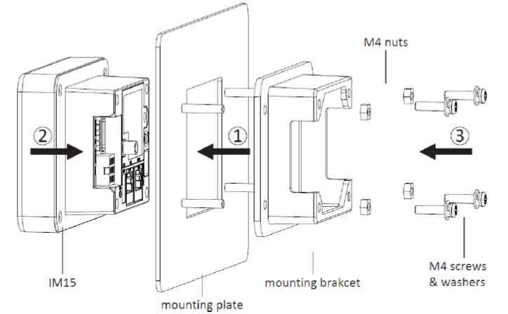
- Begin by securing the mounting bracket onto the mounting plate. The back of the mounting plate should have four M4 stud bolts that correspond to four mounting points on the mounting bracket. Slide the mounting bracket onto the bolts, then use M4 nuts to secure it in place.
- After the mounting bracket is secured to the mounting plate, insert the IM25 unit through the front of the mounting plate into the mounting bracket.
- Apply a torque of 1.2 ± 0.2 Nm to the four M4 screws to secure the IM25 to the mounting bracket through its four inner mounting points.
Instructions
Power on: Plug the IM25 into an appropriate power source (7 to 48 VDC) via the MDB port, the digital IO port, or the RS232 RJ45 port.
Power off: Disconnect the IM25 from the power source it is connected to.
Contactless Transactions
When the device is ready to accept a contactless transaction, the contactless icon should appear on screen. Orient the card or NFC device parallel to the screen and then hold it at a distance of 4 cm or less directly above the contactless icon.
Code Scanner Transactions
When the device indicates on screen that it is ready to scan a 1D or 2D code, orient the code parallel to the code scanning camera and then place it directly in front of the camera.
Environmental Parameters
- Operating Temperature: -20°C ~ 70°C
- Storage Temperature: -30°C ~ 70°C
- Humidity: 5% ~ 95% (without condensation)
Maintenance and Usage
- If repairs are required, contact PAX support.
- If any cables become damaged, seek a replacement.
- Do not insert unknown materials into any port on the IM25; this may cause serious damage to the device.
- Only qualified personnel should repair this product.
- The IM25 is designed for outdoor use; however, during normal use its surface should still be keep clear of dirt and possible liquid contaminants.
- While the IM25 is designed to resist ingress of dust and liquids, it is not designed to resist pressurized liquids such as water hoses. Keep the back of the device away from dust and liquids as much as possible.
- Make sure the various cables connect to provide the appropriate voltages at the proper pins.
CAUTION: Changes or modifications not expressly approved by the party responsible for compliance could void the user’s authority to operate the equipment.
FCC Compliance statement
This device complies with Part 15 of the FCC Rules. Operation is subject to the following two conditions:
1) This device may not cause harmful interference, and
2) This device must accept any interference received, including interference that may cause undesired operation.
Warning
This equipment has been tested and found to comply with the limits for a Class B digital device, pursuant to Part 15 of the FCC Rules. These limits are designed to provide reasonable protection against harmful interference in a residential installation.
This equipment generates, uses and can radiate radio frequency energy and, if not installed and used in accordance with the instructions, may cause harmful interference to radio communications.
However, there is no guarantee that interference will not occur in a particular installation. If this equipment does cause harmful interference to radio or television reception, which can be determined by turning the equipment off and on, the user is encouraged to try to correct the interference by one of the following measures:
- Reorient or relocate the receiving antenna.
- Increase the separation between the equipment and receiver.
- Connect the equipment into an outlet on a circuit different from that to which the receiver is connected.
- Consult the dealer or an experienced radio/TV technician for help.
• Caution
Any changes or modifications not expressly approved by the manufacturer could void the user’s authority to operate this equipment.
• Radiation Exposure
This device complies with FCC radiation exposure limits for general environments.
INDUSTRY CANADA STATEMENT
This device complies with Industry Canada license-exempt RSS standard(s). Operation is subject to the following two conditions:
1) This device may not cause interference, and
2) This device must accept any interference, including interference that may cause undesired operation of the device.
Le présent appareil est conforme aux CNR d’Industrie Canada applicables aux appareils radio exempts de licence. L’exploitation est autorisée aux deux conditions suivantes:
1) l’appareil ne doit pas produire de brouillage, et
2) l’utilisateur de l’appareil doit accepter tout brouillage radioélectrique subi, même si le brouillage est susceptible d’en compromettre le fonctionnement.
This device and its antenna(s) must not be co-located or operating in conjunction with any other antenna or transmitter, except tested built-in radios.
Cet appareil et son antenne ne doivent pas être situés ou fonctionner en conjonction avec une autre antenne ou un autre émetteur, exception faites des radios intégrées qui ont été testées.
The Country Code Selection feature is disabled for products marketed in the US/Canada.
La fonction de sélection de l’indicatif du pays est désactivée pour les produits commercialisés aux États-Unis et au Canada.
• Radiation Exposure Statement
This equipment complies with IC radiation exposure limits set forth for an uncontrolled environment. This equipment should be installed and operated with minimum distance 20cm between the radiator & your body.
• Déclaration d’exposition aux radiations
Cet équipement est conforme aux limites d’exposition aux rayonnements IC établies pour un environnement non contrôlé. Cet équipement doit être installé et utilisé avec un minimum de 20 cm de distance entre la source de rayonnement et votre corps.

PAX Technology, Inc. reserves the right to change product technology specifications without prior notification.
PAX continually invests to maintain its high-quality products up to date with the latest certifications; therefore, a comprehensive list can be requested via the website’s contact form or through downloadable product brochures.
PAX Technology, Inc.
North American Headquarters:
8800 Baymeadows Way West
Suite #500 / Floor 5
Jacksonville, FL 32256
Phone: +1 877 859 0099
Email: [email protected]
Website: www.pax.us